



Polymaker recently worked with 3DQue Systems, a company that retrofits existing 3D printers for hands-free part removal and high-volume production. They are the first company who use PolyCast™ as support to print metal parts and automate this process with the Ultimaker S5.
Quinly automation system
3DQue’s automation system, Quinly, is a virtual printer operator, that can be installed on Raspberry PI and connected to 3D printers. When installed, Quinly can queue preloaded Gcodes, auto-level, execute part removal after a print job is completed, and start the next print job. 3DQue designed its VAAPRTM print bed that provides 500x adhesion when heated and allows easy release when cooled, without additional adhesives. Automated part removal is achieved using a gravity-assisted mechanism: Quinly incorporates a mechanical motion of the printer head/bed, to sweep off printed part, before starting the next print job. Quinly also provides real-time data, failure notification, and Livestream access to the print. By eliminating a significant portion of the manual tasks in a print job (filament still needs to be changed manually), Quinly reduces per part cost by 80%.
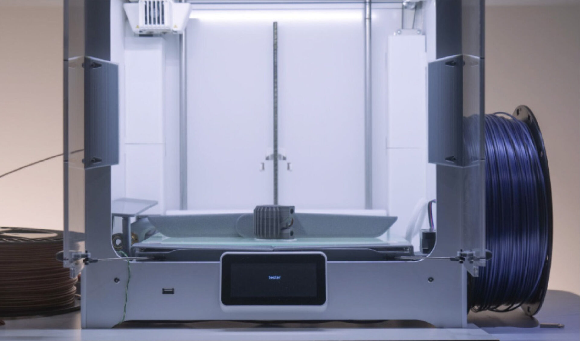
Fig (1) Quinly equipped Ultimaker
PolyCast™: Easily Removable
In this specific case, 3DQue automated metal 3D printing in a new and innovative way: Metal and PolyCast™ filament are extruded into build and support structures using a dual-head printer. PolyCast™ filament served as an effective raft material and was fully compatible with Quinly’s VAAPR™ surface. The printed rafts had excellent bed adhesion at 60°C and were fully released at 35°C. This allowed all parts to be autonomously removed from the printer via the wiper arm mechanism included in the Quinly for Ultimaker S5 automation system. The printer required only 10 minutes to cool and clear the print bed between print jobs.
Among a few other support materials 3DQue evaluated, PolyCast™ stood out for its performance in clean removal.
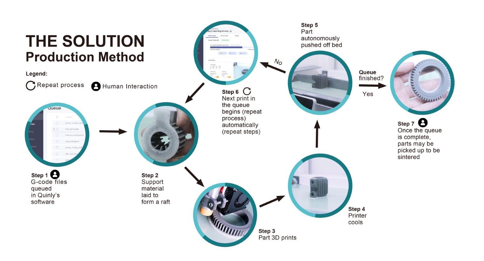
Fig (2) Flow chart for using Polycast™ as a support for metal prints before sintering
PolyCast™: Ash-Free
And then, printed parts were sintered with the rafts and supports in place. The PolyCast™ filament was burned away, leaving only 0.003% residue. Sintering without a raft was tested as well: the PolyCast™ rafts did not fuse with the metal filament and were easily removed by hand.
PolyCast™ is a PVB-based material designed for metal investment casting. It shares a similar formulation with the well-known PolySmooth™ and comes with ash-free technology that enables clean removal. PolyCast™ is also safe and easy to post-process. It is smoothable with IPA in Polysher™, or similar tools.
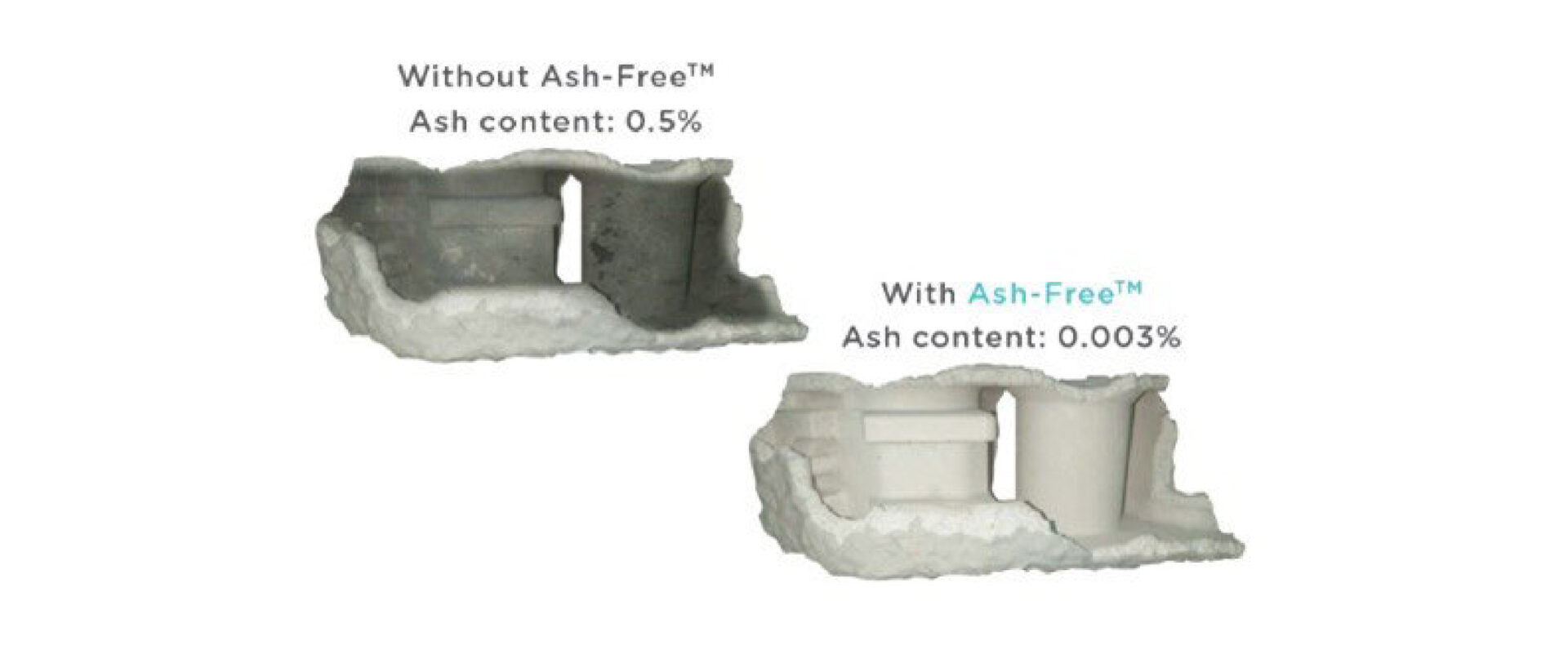
Fig (3) Ash content comparison between with Ash-Free and without Ash-Free
PolyCast™ rafts make Quinly fitted Ultimaker printers compatible with many metal filaments on the market. The raft easily slides off the bed once cooled, making metal filament bed adhesion issues a thing of the past.
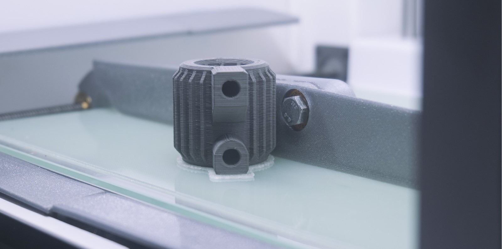
Demonstrated by 3Qque, PolyCast opens a potential avenue to mainstream manufacturing processes of metal parts. Beyond investment casting, in which PolyCast has gained significant attention, this case study brings an inspiring application of PolyCast. Due to the clean burnout nature of PolyCast, complex geometry in metal part fabrication is made possible by printing the PolyCast filament as support to the metal filament.
What’s more? Automation of the printing and part harvesting, enabled by systems such as Quinly, could make high-volume complex metal part production feasible and economically competitive.

Perfectly clear 3D printed parts are possible with PolySmooth™ and here is the story of one of our customers. Mattias has shared with us his process creating a pair of lenses for the kitchen fan lights.
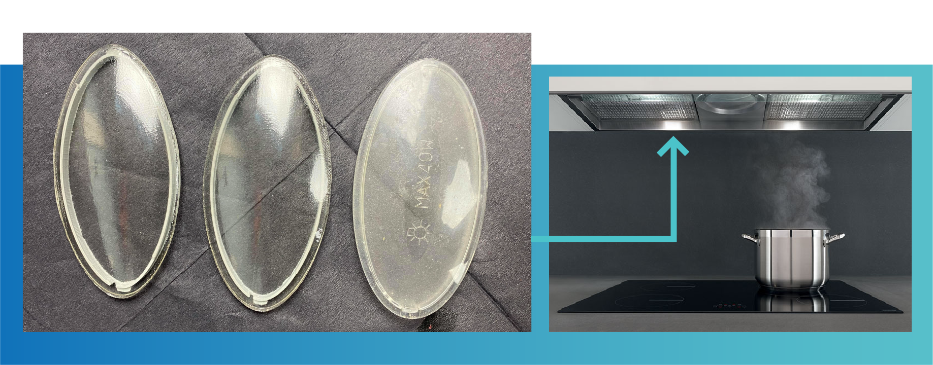
From: Mattias Lundberg
July 22nd 2021
I made a thing! well, two actually. I needed to fix something in my home and like so many times before I resorted to 3d printing and my favourite filament Polysmooth. Hi, My name is Mattias Lundberg and I love 3D printing. I´ve been doing this as a hobbyist for 6 years now and love to make the impossible possible and to push the limits just to be able to hold the printed part in my hand or see it functioning the
way it was intended.
My task at hand this time was the light covers on my kitchen fan. Originally the lamps were very hot so my first attempt three years ago was with a super clear heat resistant material that...melted. But I realised that after all these years the original lights had been phased out to LEDs. THEY dont produce heat! Bingo! Lets try Polysmooth transparent!
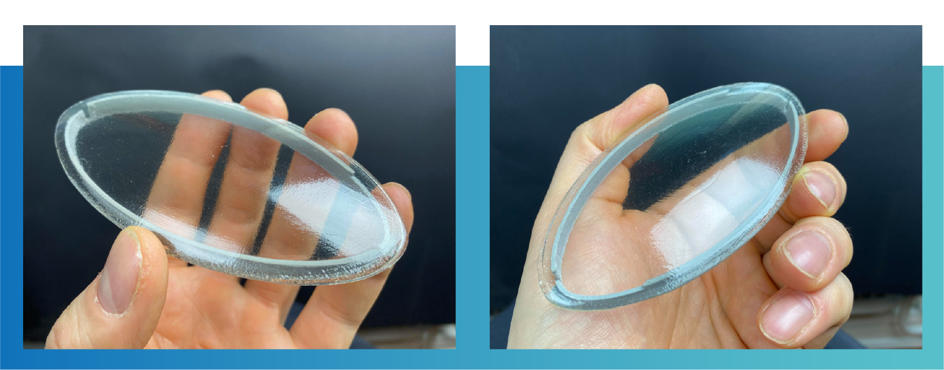
The object this time is a simple yet complex shape that had to be separated into the lens as one part and the frame with clips as the other. The frame with flexible clips had to be printed separately with a 0.4 nozzle while the lens must be printed with a thicker nozzle and only as a single perimeter wall.
This products really is made for resin printing but when you are hell bent to make it with an FDM printer that's what you gotta do right.
Something really important in order to reach success is to know not only your personal limitations but also the slicers, printers and the filaments limitations and roll with it and use them to your advantage. In short, trick the printer and filament in doing what you want it to.
I tried many different orientations and techniques and had a lot of failed prints and semi good results until I found the way!
This is a round bulgy object, it needs to stand on its edge, have low layer height and around 190 degrees nozzle temp. And printed in vase mode or spiralized as its called in Cura.
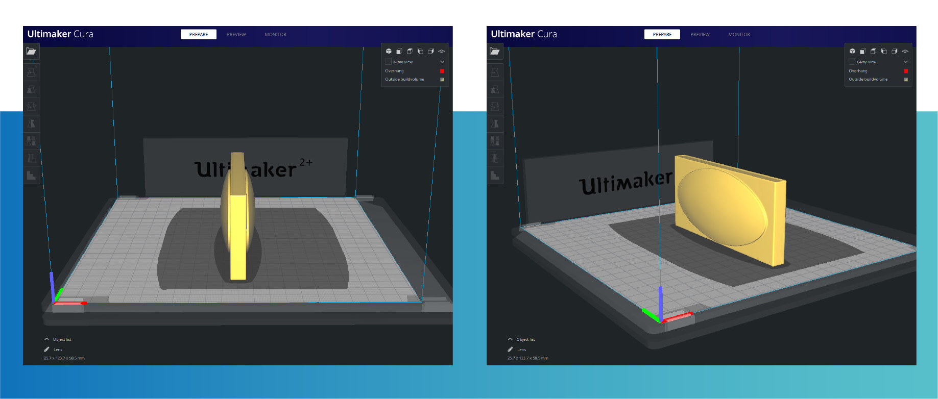
Therefore I made a single perimeter box with the lenses bulging out on the longer sides and printed it really thick (2 mm) to make it look like the original piece. This way the nozzle could go round and round printing both lenses without any disturbances.
Next step was to simply cut it out of the box walls and treat it with 100% Isopropanol, let it dry and sand it before final IPA treatment and done! I was holding two perfectly shaped, very clear and sturdy lens shaped covers in my hand. The frame was glued on and the whole piece was snapped into place and I know its gonna last a long long time. Thank you Polymaker.
Check out Mattias post and video of the prints on facebook:
https://www.facebook.com/groups/polymaker/posts/2728308607433197/
3D printing technology has become a preferred method for DIY persons, however, the model post-processing to remove layers, the bonding between different parts, painting and so on stay a challenge. A few weeks ago, we noticed an amazing Halo cosplay on social media, the costume was 3d printed using PolyLite™ PLA. This amazing work was done by Alpha to Zeta Industries, and we were very excited to contact them and ask if they would like to share their professional experience with us. We were glad to hear back from Anthony from Alpha to Zeta Industries, they kindly explained all the manufacturing process to achieve such results and were also happy to share it with our community.
If you are interested in cosplays or have challenges building your costumes, you can reach them on social media: Facebook or Instagram. If you are interested in Halo cosplay, you can also visit their group of Halo cosplayers on 405th.com. They have a lot of knowledge to share and are happy to assist new members.
Here is the reply from Anthony explaining how he post-processed his costume:
Hello,
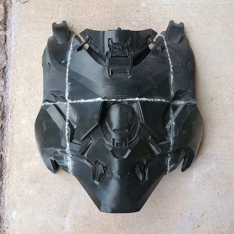
Thank you for reaching out to us about working with Polylite PLA. We are big fans of the video game franchise Halo. And for about 3 years now we have been creating costumes from that franchise under our page, Alpha to Zeta Industries (on Instagram and Facebook). Our primary tool to create these costumes is our 3D printer, our Lulzbot Taz 6. Just recently we created a new version of our Spartan Recluse suit using Polylite PLA. To create this suit, we started with files from Halo 5 Guardians. From there we extensively reworked the models for 3D printing and added details. Once we were ready to print, we selected Polylite PLA due to the positive results we have had with it in the past. To describe the process, I will talk you through how we finished the chest armor. Picture 1 (Attached) is a picture of the raw 3D print fresh off the printer and assembled.
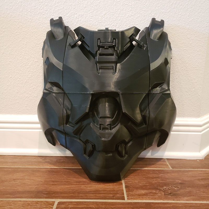
Picture 1
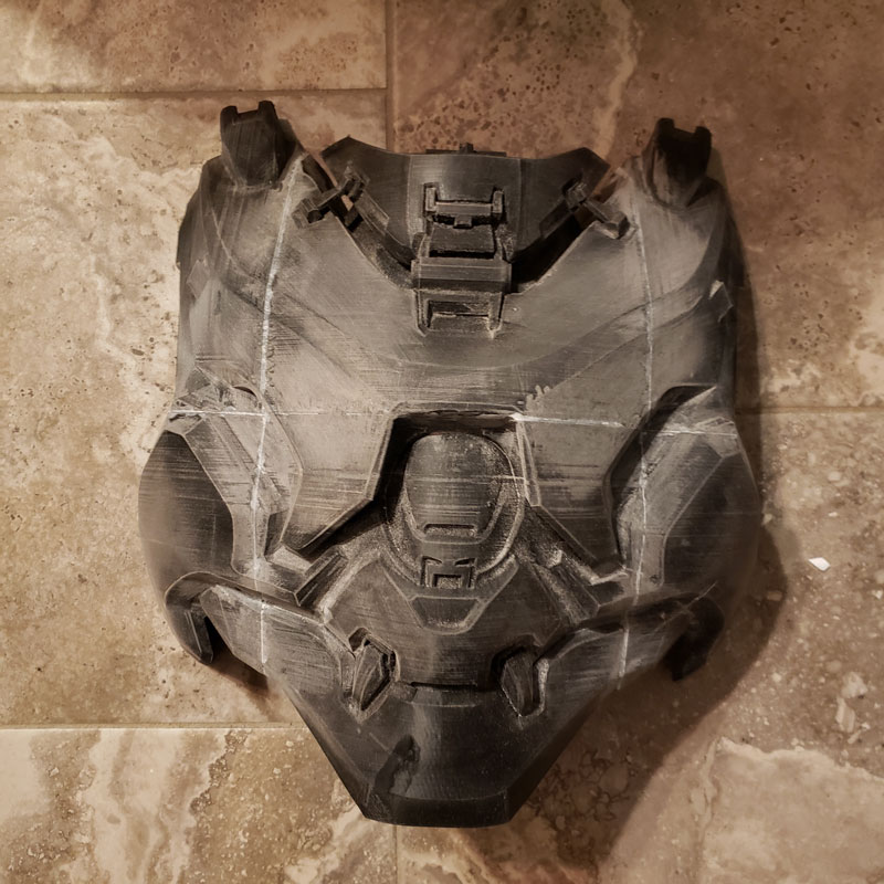
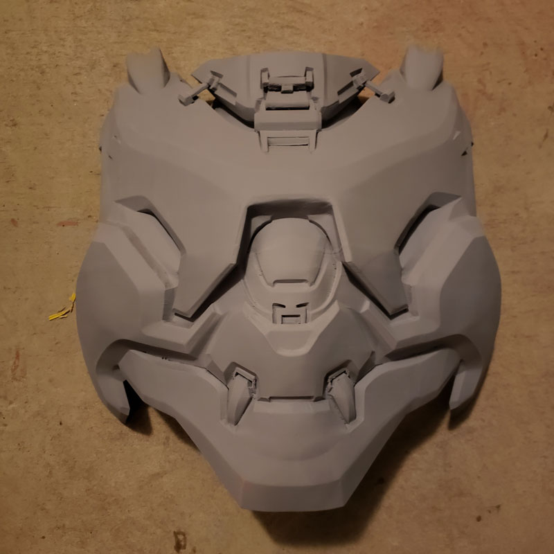
The first problem that we tackled was hiding the seams. This is accomplished by filling each seam with a mixture of baby powder and super glue (CA). Once the seam is filled, an accelerant is added to solidify the bond. We then sand down these seams to make the area flush. Picture 2 (Attached) shows the seams after they have been filled. And Picture 3 (attached) shows them after they have been sanded down.
Picture 2
Picture 3
We then cover the whole piece with a product from Smooth-On called XTC3D. This is a two-part epoxy that fills a large amount of the layer lines while also adding a degree of strength. Once the epoxy has cured, we begin the extensive process of sanding. This process is three parts. First, we apply Bondo spot putty to the piece in any areas that need filling. Once it is dry, we sand the piece down with a high to medium grit sandpaper. Then, lastly, we apply filler primer to the whole piece. This process is repeated until the piece is smoothed to our satisfaction. Picture 4 (Attached) shows the piece after one of the rounds of filler primer.
Picture 4
Once the print lines and any other imperfections are filled to our liking, we then wet sand the whole piece up to 1500 grit sandpaper. This ensures an extremely smooth surface. Once wet sanding is complete the fun really begins. Time for color. We first put down a metallic base coat on the piece. This base coat is then covered with a clear coat. This way when the main color is scrapped off the metal will show for a desired ‘weathered’ look. Picture 5 (Attached) is the piece with the basecoat applied.
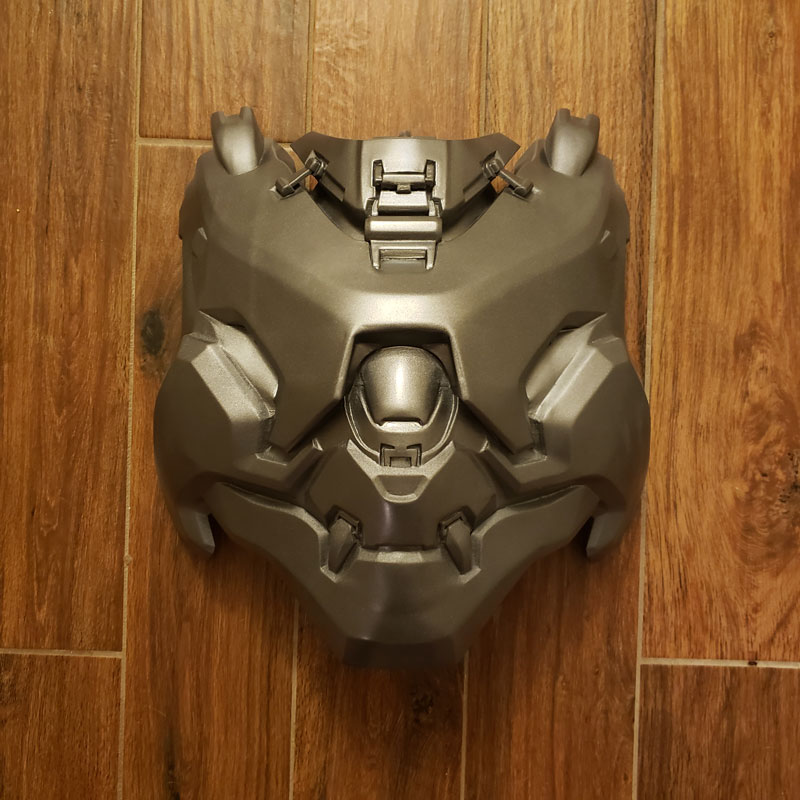
Picture 5
After this has dried completely, we then apply the base color and any other desired details. The final result is the piece ready for cosplay! Picture 6 (attached) shows the completed piece.
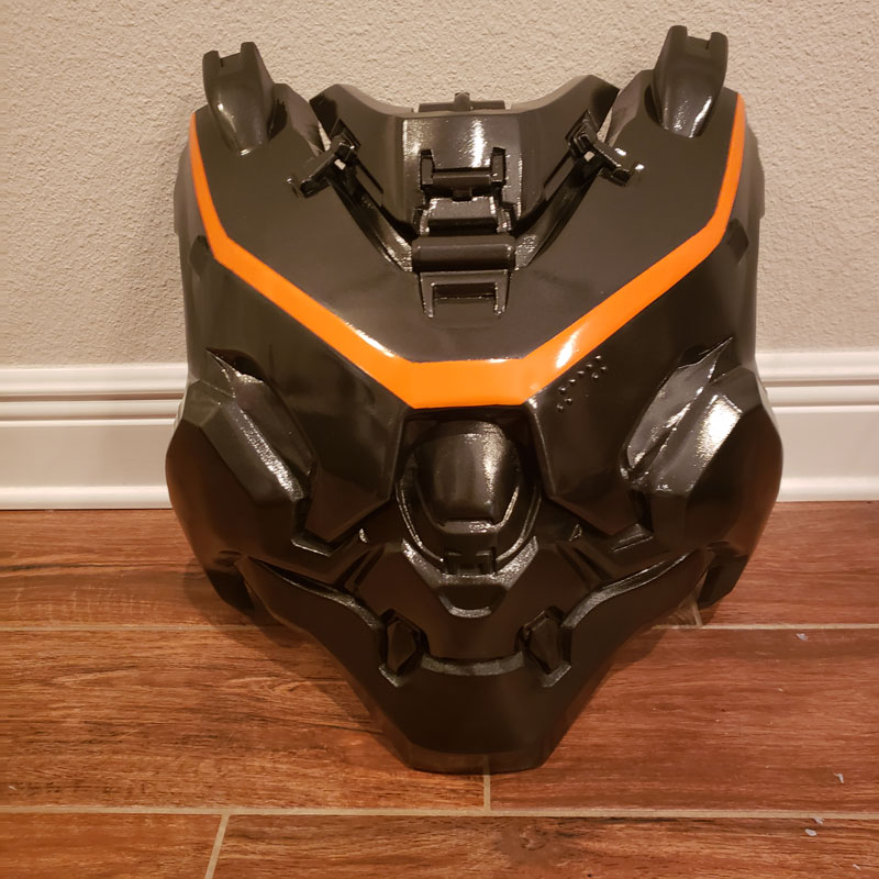
Picture 6
It can be a process. But our goal is to garner the smoothest finish possible on our costumes and this process has worked great for us so far. The base print quality afforded by Polylite PLA definitely makes it easier than it has been in the past. To close, if anyone is interested in costuming or if there are any questions please feel free to message us on our social media channels. Lastly, if you are interested in Halo cosplay specifically checkout the 405th.com. The 405th is a group of Halo cosplayers who have a wealth of knowledge and are happy to be of service to new members.
Thanks again!
-Anthony
Alpha to Zeta Industries
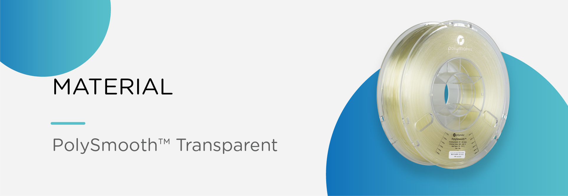
PolySmooth™ Transparent can create some of the highest transparency parts that can be printed with FFF/FDM technology. Following our tips below should help you on your way to creating highly transparent parts with glass-like clarity.
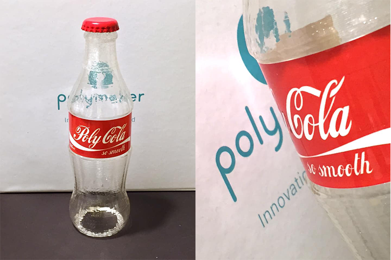
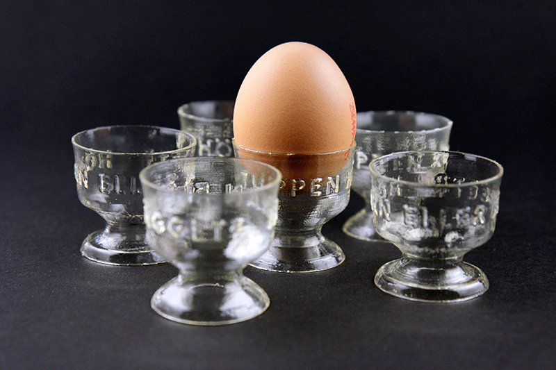
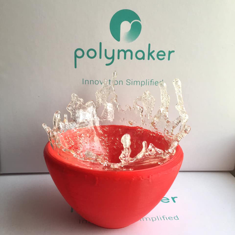
The ability to create highly transparent parts is a great tool for makers and polished parts become completely water and oil resistant. Below we showcase some creative ideas from our community!
Besides, Transparent PolySmooth™ print is watertight and oil-proof. Here are some impressive examples.
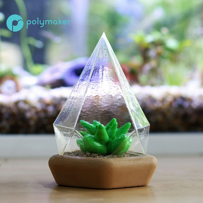
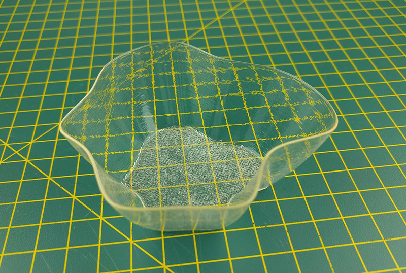
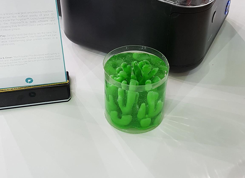
Printing Tips
- Make sure that PolySmooth™ is dried before printing it, this ensures there won’t be any bubbles generated during the printing process. (Drying setting: 60℃ for 12hours) PolySmooth™ is a hygroscopic material and can absorb moisture from the air, this can cause bubbles in the filament when printing and will not produce the best optical clarity of the transparent parts. [Compulsory]
- Choose vase mode (spiral mode) or print in a single shell. Printing one shell will produce the most transparent results as multiple shells will bend the light more. [Compulsory]
- Use a bigger nozzle size. The polishing process of PolySmooth™ will soften the material, this means that thin parts may buckle under their own weight when polishing. Using a larger nozzle will help add mass and strength to the single shell walls allowing more complex transparent shapes. The parts will re-harden after the polishing process. [Optional]
- Decrease the printing temperature. A higher printing temperature will cause more bubbles to form between the layers, PolySmooth™ will print at temperatures as low as 160°C however we find that 180°C produces the best results.
- Use the Polysher™ to polish the models. The Polysher™ delivers a constant stream of IPA to the PolySmooth™ models which will gently and evenly turn the surface transparent. As your walls will be very thin, its best to polish in short bursts allowing for some drying time in between cycles. 5-10 minute cycles with 5 minutes inactive drying time inside the Polysher™ delivers the best results. A single-walled print should be nicely polished in 2-3 cycles of 5 minutes each.
- Alternatively spray alcohol onto the print surface evenly, repeating this operation until the print becomes transparent. Spray IPA all over the model and completely coast all surfaces, the majority of this IPA will evaporate away so, you will need to repeat the process every 5 minutes for 4-5 coats. Don’t touch the polished surface until it has resolidified [Compulsory]
- Remember to polish both sides of the shell, internal walls can be shielded from polishing in certain geometries. In some case,IPA can be poured into enclosed vessels and shaken about to coat all surfaces. Remember to empty out any residual IPA if using this technique as the polishing process will be too aggressive with pools of IPA contained inside. [Compulsory]
- A fan can be used to accelerate the drying and solidification process. Point a fan at your model and leave for a few hours, the surface will harden and can be handled after 10 minutes, it will then take a further 24 hours to fully harden. [Optional]
Knowing these tips, you ought to be able to print your own transparent models seen in the pictures above.
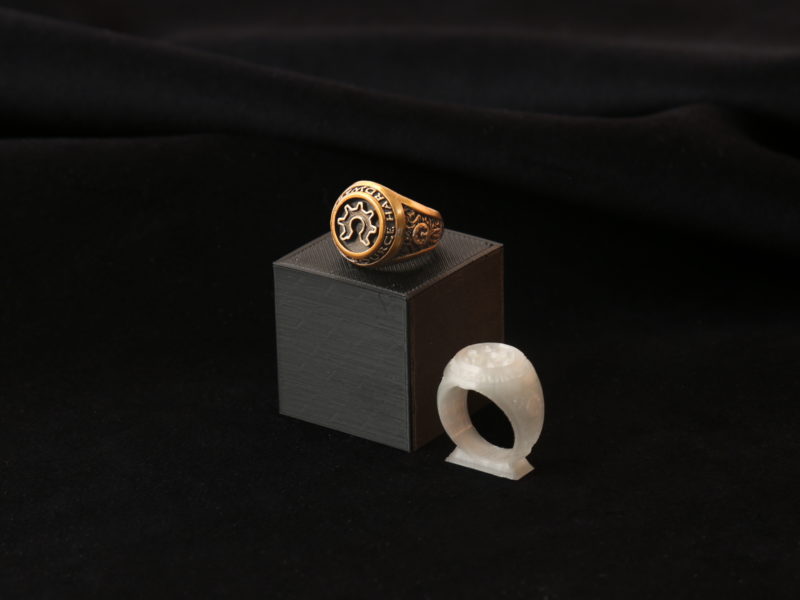
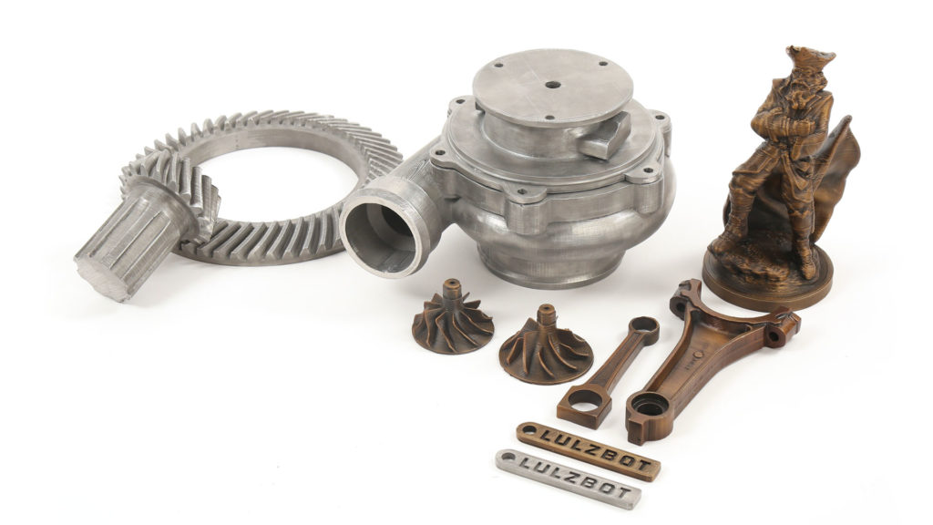
Lulzbot has just released their PolyCast™ bundles alongside a comprehensive guide for turning your 3D printed parts into metal parts. This tutorial shows the workflow from CAD to metal part using PolyCast™ 3D printing filament with Ash-Free™ technology. The unique properties of PolyCast™ allow for a very clean burn out when curing ceramic molds during the investment casting process. This leaves a very clean surface on the inside of the ceramic mold which is perfect for metal casting. Ash-Free™ technology typically leaves an ash residue of 0.003%. The Lulzbot Taz 6 has a very large build volume capable of producing very large patterns for investment metal casting. Paired with their wide range of interchangeable tool heads, PolyCast™ patterns can be printed extremely fast with their MOARstruder (1.2mm nozzle) or users can achieve incredible detail suitable for jewelry with their new Aerostruder V2 Micro (0.25mm nozzle) and everything in between.
"3D printing patterns for investment casting is increasingly becoming the go-to solution for artisans, engineers, and industrial professionals alike. With LulzBot 3D Printers and PolyCast™, users are able to test designs, iterate faster, and quickly produce short runs while reducing expensive tooling and long lead times. At a fraction of the cost of most additive manufacturing investment casting solutions, LulzBot 3D Printers enable companies of all sizes to speed innovation while reducing costs." - Lulzbot
Read their full article here: https://www.lulzbot.com/learn/tutorials/3d-print-patterns-investment-casting
FRICTION WELDING
In the early days of 3D printing when the first printers were being developed, the only material the inventors could get their hands on was ABS. This was largely due to the availability of ABS welding rods which were already being produced at the time and happened to a convenient shape and diameter. So it seems this historic relationship between 3D printing and plastic welding is deeply routed in the extrusion based technology. In this article and tutorial I’d like to show you how to harness this technique and explore its full potential. What makes this process so easy nowadays is the availability of welding rod, which in this case is the filament you used to print your models. At its heart, friction welding is the process of welding two objects together by harnessing the heat generated by friction. To generate the heat required to melt the plastic you’ll need a rotary tool. The collar on my rotary tool better suits a 2.85mm – 3mm filament and in the video I’m using PolyMax as that was the same material I used to print my objects. Once the filament is spinning in the rotary tool the idea is to gently feed the fast spinning filament into your seem line. The friction created from the rotation raises the filament and model to their glass transition temperature at which point you feed the filament into the seem. There are a few different techniques to apply when welding, each with their own benefits.
Pulling Technique
In this technique you want to position the rotary tool so the filament is pulling along the seem line. This way the edge of the filament has time to cut a channel into the two sides.Angle the rotary tool to around 45°. During the cutting process the friction raises the temperature of the filament and it subsequently melts into the channel. This is a very good welding technique as the molten plastic penetrates down through the layers and after a bit of practice with pressure and speed you can get the plastic filling the channel nicely. Take note of the direction of your rotary tool. My rotary tool spins clockwise, this means that the rapidly cooling plastic is always being dragged in a clockwise motion and you tend to get a larger build up of material on the right hand side of the weld. So you may need to do another pass on the left hand side to make a truely seem less weld.
Small Circles Technique
This technique is borrowed straight from MIG welding. This is the technique I was taught when welding steel, the trick is to drag the molten plastic over the seem line stitching the two parts together. When done properly its a great one time welding technique and if you use contrasting colours to weld with you should be able to see the different hues blending in the weld. The angle of the rotary tool wants to be raised to around 70° – 80° this means that more heat is focused in the tip of the filament and as it passes over the seem line it stitches the two parts together. Generally the weld also sits proud of the surface which is ideal if you want to grind and sand back your weld to a flat surface. The downside to this technique is that it doesn’t cut a deep channel into the printed parts. This means you end up with a surface weld which isn’t as strong as the pull weld. If your looking purely for aesthetics then this is a great looking weld as the concentric circles mimic that of a metal weld. Try combining the two techniques for a strong and seem less weld.
Right to Left Technique
Also a great technique for the one hit weld. If your rotary tool spins anti clockwise then this technique becomes left to right instead. The advantage over the pull weld is the the excess material that was building up on the right hand side of the weld is now sitting on top of the seem. This technique also cuts a channel, making it stronger than the small circles weld. However the penetration depth doesn’t match that of the pulling technique. You can adjust the rotary tool to a shallow angle when using this technique and the shallower you go the deeper your channel will become.
Gap and Hole Filling
If you have already bonded your parts together and are happy with the strength of the joint. You can use a plastic with a lower printing temperature (therefore lower melting temperature) to fill small gaps and holes. By using a filament with a lower melting temperature you can ensure you build enough heat into the filament without making the gap or hole any larger. Its best to angle the rotary tool to 90° to the part, this way the smallest surface area of plastic is heating up ensuring that it melts quickest. Combine the small circles technique with a lower melting filament for best results.
TAKING PRINTED PARTS THE EXTRA MILE
3D printing has changed the way we would traditionally manufacture. Additive manufacturing is much more efficient, faster and cheaper than the more conventional way of modeling. The fact remains though, that the quality of model you get from a printer doesn’t match our expectations. Our perception of a plastic part is shaped by subtractive mass manufacturing. We expect smooth glossy surfaces as standard to which the bar has been set very high for a number of decades. To then show a newcomer a printed part, with its geometry flaws, rough surface and layer resolution, the promise of what they had in mind seems unimpressive compared to what they know of plastic parts. In this article we will discuss the post processing options available to FFF/FDM printed parts, showing you how to take your prints through the threshold and into the league of high quality parts set by the industry, only difference being, your parts are unique.
For this project, I want to demonstrate how to achieve a professional finish using only 3D printed parts, filler and paint. As more and more new printer manufactures claim they can print at 10 microns layer resolution, you would assume eventually the layer resolution and surface roughness would become negligible. But from what I’ve seen anything under 100 microns makes little or no difference to surface smoothness and print quality. This fact is the limitation of FFF/FDM printers, essentially this is the heart of the technology and to truly overcome the issue you must post process to achieve the professional quality we are all used too.
The first issue is size, of course there are large scale printers that can print life size busts in one go, but these machines are costly and do not represent the vast majority of desktop users. So to finish a life sized bust, you must first split your model and then print in sections. For the Iron Man, I used the Makerbot Replicator 2. This is still my go to printer, today it may be considered “retro” but it is a fantastic printer and very reliable for printing PLA. Choosing a suitable material for the job is essential to the project. For the iron man bust, I chose PolyMax, PolyMax offers great detail and surface quality which vastly saves time when starting the sanding process. The other main benefit is that PolyMax is warp free. This is particularly important as my model is split into sections and joining warped sections can leave huge voids and create problems down the line.
The next hurdle is joining these sections, initially I tested with superglue but found that it doesn’t bond PolyMax very well. My next choice was a two part epoxy resin glue, this bonds the printed parts very well. Usually I would key up any surface before glueing parts together, however the layer resolution mimics the deep scratches produced by coarse sandpaper allowing a greater surface area for the glue to bond. While I’m a big fan of this glue as it really will stick just about anything to everything, its not very nice to work with, the smell is extremely strong and you can often feel light headed if your not in a properly ventilated area or aren’t using the correct respiratory gear. To avoid using the toxic glue I moved on to a friction welding technique, this is a very good process first introduced to me by one of our filament distributors in Australia. The idea is to use a short length of the same filament you used to print your model with, and spin the filament in a rotary tool. Then gently feed the fast spinning filament into your seam line. The friction created from the rotation raises the filament and model to their glass transition temperature at which point you feed the filament into the seam. This is a great technique for filling small gaps although the process is tricky and requires a steady hand. The strength of joint you achieve should rival that of a deposited layer, and the benefit that theres no foreign material being added to the joint makes this process perfect for joining parts. Once all the sections are joined, you can start to sand the PLA.
The softening temperature of most PLA’s is around 60°C, which can easily be reached by the friction created with a moderate sanding. This must be considered when working your surfaces. For this reason I would always recommend printing your model with at least 3 shells if its a surface you intend to sand. PLA is not a good conductor of heat, so the plastic tends to hold on to its residual heat from the sanding. Take often breaks to allow the plastic to cool, whilst also using water to sand with. The use of water not only helps dissipate the heat from the sanding it leaves you with a smoother surface and stops your sandpaper clogging. Use a block of high density foam to back your sandpaper, this will even the pressure from your fingers and leave you with a much flatter surface. As the PolyMax gets nearer the softening temperature, you’ll notice long strands rolling up between the sandpaper and your model, at this point your sanding is at its more efficient and you can remove the most plastic. Although its a very good indication to slow down or stop to let the surface cool .If your preparing for a primer and then colour on top, don’t stop sanding until all the layers have been eliminated. The primer will fill some very fine surface gaps, but don’t expect to build up paint to hide your layers. A 240 grit sand is sufficient for primer. Inevitably there will be some minor fluctuations between printed parts, which can create little steps once parts are joined. to solve this problem, I used a two part body filler. This is perfect for building up areas and filling gaps, be sparing with the filler though, remember less is more. Its much easier to build up thin layers than sand down big chunks. The filler sands very nicely and you can get a really high quality surface, however, the PLA and the filler will sand at different rates, for me the filler was disappearing quicker than the plastic so keep this in mind when building up steps. Try to paste your filler on both sides of the step, this way you don’t get a hard edge where the plastic meets the filler. Once you have filled all your seams and sanded your surface, its time to apply a primer.
I used an aerosol high build modelers’ primer, much like the filler try to avoid putting too heavier coat on. It will take longer to dry, has the tendency to run and drip and will spoil all the detail you’ve slaved over. Move your hand fast and make swiping passes, focus on keeping your hand a consistent distance away from your model, around 30 cm. Most aerosol primers will tack off in 10 minutes, so apply thin coats every 10 minutes and then leave overnight before you touch the model again. Where the surface may seem dry, its likely that some of the layers underneath can still be wet, this can cause fingerprints in the paint and even cause the top surface to slide. The paint needs sufficient time for the thinners to permeate the surface and evaporate. See the back of the can for proper drying times, but as a rule of thumb, overnight should be sufficient. The next day you can start working the primer, the primer will sand very quickly and is a delight to work after trawling through PLA and filler dust. Start with at least 400 grit sandpaper and work up, if you need a coarser paper then your problem lays beneath the primer and you’ll have to re-evaluate your initial PLA sanding. Always use water when sanding primer, your sandpaper will clog up very quickly otherwise and it will leave you a smoother surface. I repeated this step several times until I had a good coverage of primer all over my model.
If your primer is white and matte, which most are, its hard to tell if there are any low points or dips on the surface of your model. Matte finishes are fantastic for hiding little undulations, get them out now instead of finding them in your lacquer. A good technique is applying a witness coat to your model. This is a very fine speckle in a contrasting colour to your primer. You want the speckles all over whilst not applying too much paint. The point is that when you sand the witness layer you’ll leave paint speckles in the low spots and sand away everything else. This helps indicate where to apply filler if its really bad or where to carry on sanding. Once you have a lovely primed surface, rub the primer one last time with 1000+ grit sandpaper until its completely flat.
Your model is now ready for the top coat, for the Iron Man bust, I required two colours. Pick which colour you want to paint first carefully, you want to pick the colour that will require the least amount of masking. It was far easier painting all the areas red first and then covering with gold. As a general rule paint from light to dark, this is so your light colours wont be effected by the darker undercoat. Yellow is a particularly weak colour and almost everything apart from a white base will show through. Blow away any dust from your model and degrease the surface. Apply your top coat in a similar fashion to your primer, move your hand very fast at first and slowly build up colour, you really don’t want a run in the paint at this stage. So if your nervous hold the can a little further away. Once finished leave the paint a good 24hrs to harden before applying any masking tape. This is one of the most common problems with painting and often the tape leaves marks in paint thats not fully cured. Carefully mask your model and then apply your second colour, wait until its fully dry before removing the masking tape. At this point Iron man just needs a few highlights and low lights to tie the paint job together. I applied black with an artists brush in any seams to give depth to the model and highlighted any bolts or shiny parts and voila!
The finishing process really requires a lot of patience so try not to rush any stage as its very frustrating when it goes wrong. It can be one of the most challenging and rewarding processes to take a model from the print bed to something you could actually sell. But be careful as you walk a fine line between Tony Stark and Fred Flintstone.
The PolyPearl Tower is Polymaker’s new model designed to test your 3D printer and filament to their limits! The popular 3D Benchy model has become the go to print for users looking to optimize their printers and software settings. However, with the development in filaments and printers over the last couple years, the Benchy model only serves as an entry level when pushing your printer to the limits. Most printers PLA settings will produce a solid Benchy, which is why we have created the much more challenging PolyPearl Tower. With inspiration drawn from the famous Oriental Pearl Tower located down the road from Polymaker’s Headquarters in Shanghai, this is an architectural model…. with a twist. This model is designed to be printed without supports, within a couple hours. We recommend using 0.1mm layer height. You can download the .STL file here. The main features of the PolyPearl Tower are as follows:-
45° Overhangs
Usually, 45° is referred to as the critical angle that printers can handle without using support material on a given model. The three supporting legs of the PolyPearl Tower are all at printed at 45°. Check the underside of these pillars after printing, they should be smooth and uniform, if you find the pillars are messy and non-linear, try increasing cooling and decreasing temperature.
Acute Slopes
Featuring an acute slope of 9° this feature will test your printers ability to extrude uniformly. This is also a good test of the filament, as variations in diameter and consistency will result in gaps or non-circular rings. Tweak your extrusion multiplier to perfect the acute slope, this feature can also be affected by your infill percentage. A low infill percentage will not provide the necessary support for the rings to form neatly. Still having trouble with acute slopes? Try increasing the number of top solid layers on your print.
Fine Details
Fine details are a challenge for any printer. The lower ball of the PolyPearl Tower features tiny circular indents around the center. Check the form and roundness of these holes, they should be round on both sides of the center band. You can compare the top indents against the bottom to see if the layer compression has affected their roundness. On all our test models we never found a perfect set.
The tiny pillars on the front of the pavilion are one of the most challenging aspects of this model. Being very thin, angled and able to support the bridge of the pavilion roof is surely a tough test for any 3D printer. This is a good place to test your retraction settings, aim for clean pillars with no strings in between. The bridge on top should be well formed and also curved. This aspect of the print is almost impossible to perfect so good luck trying!
Overhangs
On both of the ball sections of the PolyPearl tower, you will find a small overhang section. Inspect the form of these details and compare the top against the bottom. The bottom should be well formed, circular and flat. The top overhang is much trickier to perfect, check the sharpness compared to the bottom. This feature is affected by the number of shells/perimeters you choose and how you choose to print them. We suggest inside-out to get the best edge on the overhang. The underside of the balls themselves ranges from 90° to 0°, the top ball, in particular, has less support so keep an eye out for the roundness near the base of the top ball.
Extrusion
To achieve the perfect extrusion settings there should be no indication of where the layer has started and stopped. In this picture, we have used PolyWood to demonstrate a perfect extrusion. Play with your extrusion and retraction settings to achieve the perfect extrusion. Using a matte finish material like PolyWood helps blend the layers also!
Roundness
Check the roundness of the balls on the PolyPearl Tower model. These balls should be consistent and spherical. Play with your speed settings to optimize roundness, most PLA’s will print happily at 60mm/s.
Fine Bridging and Smooth Curves
While the distance of this bridge is not that impressive, the triple helix design of the PolyPearl Tower will test your printers bridging capabilities on 4 different orientations in one print. We found this change in orientation resulted in some messy bridging on one or two of the sections. Play with your cooling and bridging settings to optimize the fine bridging. You should also notice a smooth curve up the sides of the triple helix. Key an eye out for layer shifts where the bridges meet the helix.
Top Layer Fill
The Top Layer Fill on the Polymaker Logo should be completely filled in. This is effected by the number of Top Solid Layers you choose and also by the amount of shells/perimeters you choose. Too many shells/perimeters and you will be left with a gap in the top surface.
Dimensional Accuracy
Finally, check the dimensional accuracy of your print against the CAD measurements. The overall height of the PolyPearl tower is 99mm allowing to print on virtually every 3D printer on the market. Use calipers to measure the diameter of the top and bottom balls respectively. You can then create a ratio for your printer so you know how to design and scale for your machine.
Good luck printing the PolyPearl Tower, please share your results on our social media pages and start a discussion within the community!
The Pumpkin Painting tutorial is an easy to follow introduction to painting your polished prints. Using PolySmooth™ and the Polysher™ an airbrush and some acrylic paints you can create a realistic pumpkin model that won’t look 3D printed. PolySmooth™ is the perfect material for painting. The Polysher™ smooths the layers to prepare a clean surface which the paint adheres to very well.